

As we know, any internal combustion engine works thanks to combustion, a chemical reaction between fuel (petrol, diesel, methane and so on) and oxidiser (air) that releases the energy used to move the pistons. The amount of energy released by combustion depends on the amount of fuel used: the greater the quantity, the greater the energy released, up to the point where, for a given combustion chamber volume, there is too little air to guarantee good combustion and the engine floods. But combustion also depends on the quality of the reactants: the octane rating of the fuel, and also the density of the air drawn in. Let us go back to the power formula shown in the article on engine subdivision. (click here to read the article)
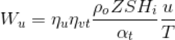
Power Wu is directly proportional to air density ρo, and there are two ways of increasing that density and, as a result, the power output:
• increasing the pressure, by means of turbochargers.
• reducing the temperature, by means of heat exchangers, which in the automotive world are known as intercoolers.
The turbocharger is a mechanical device that increases the density of the air using the energy contained in the exhaust gases. The device can be split into two sub-systems: the compressor (to the left of the drive shaft At) and the turbine (to the right).
Pictured: operating diagram of a generic turbocharger
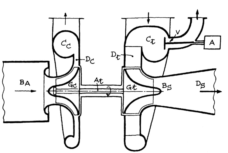
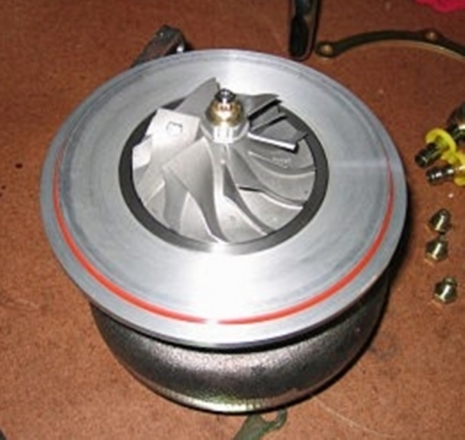
The compressor takes in the air to be processed through the inlet Ba, which leads straight to the centrifugal impeller Gc. The impeller has backward-curved blades, the result of fluid dynamics research alongside the development of materials that are ever more resistant both mechanically and thermally. That shape contributes in part to the increase in pressure, since it is the diffuser Dc that converts the kinetic energy of the air into the share of pressure still missing for the operating conditions. After that, the air is sent to the volute Cc, which delivers it to the engine or to the intercooler, where one is fitted.
Pictured: blades of a compressor impeller
On petrol engines there may be a valve placed between the throttle and the compressor, known as the pop-off, or blow-off, valve. Its job is to vent off the compressed air when the driver lifts off. On a lift-off the compressor in fact carries on processing air through the inertia of the impeller and sends it towards the throttle. With the throttle butterfly closed, it acts as a barrier and pushes the compressed air back towards the impeller, producing what is known as water hammer, a fluid dynamic phenomenon that is damaging to the turbocharger.
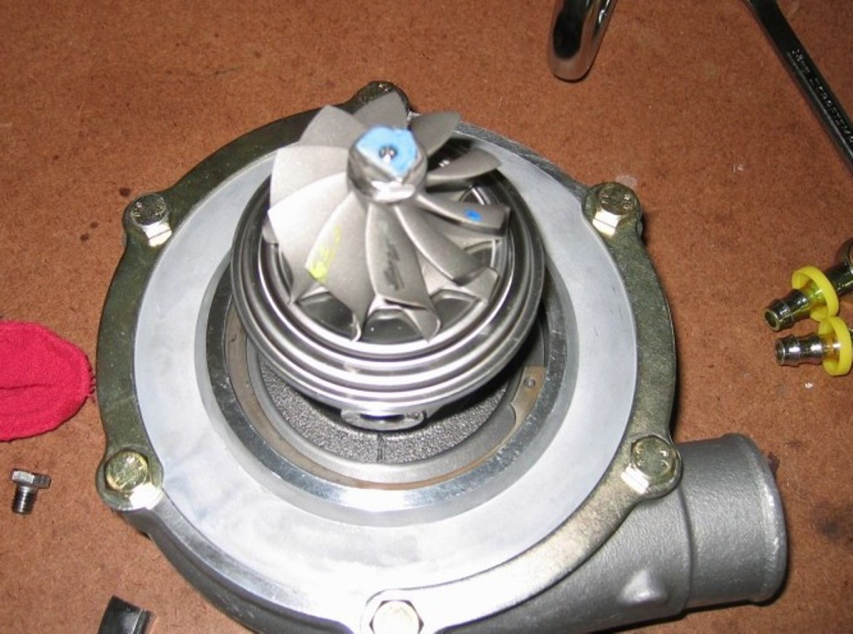
Once the charge has been used for combustion and expelled by the engine, it is sent to the turbine, channelling itself into the volute Ct. The charge is then directed into the nozzle ring Dt. The job of this nozzle ring is to give the hot air a mainly tangential motion relative to the turbine blades, so as to maximise the conversion of thermal energy into kinetic energy. The turbine blades too have been developed along the same lines as those of the compressor.
Pictured: blades of a turbine wheel
It can happen that the energy contained in the exhaust gases becomes critical and could cause malfunctions or damage to the turbocharger. This is why the so-called waste-gate valve V is used, venting the excess hot air to atmosphere through a duct located downstream of the turbine. The opening of the valve is regulated by an electronic actuator A. Once they have passed through the wheel, the exhaust gases leave through the outlet Bs. Sometimes a diffuser Ds can be fitted at the outlet so that the turbine can recover as much further useful energy as possible. The kinetic energy obtained is sent to the compressor impeller through the drive shaft At.
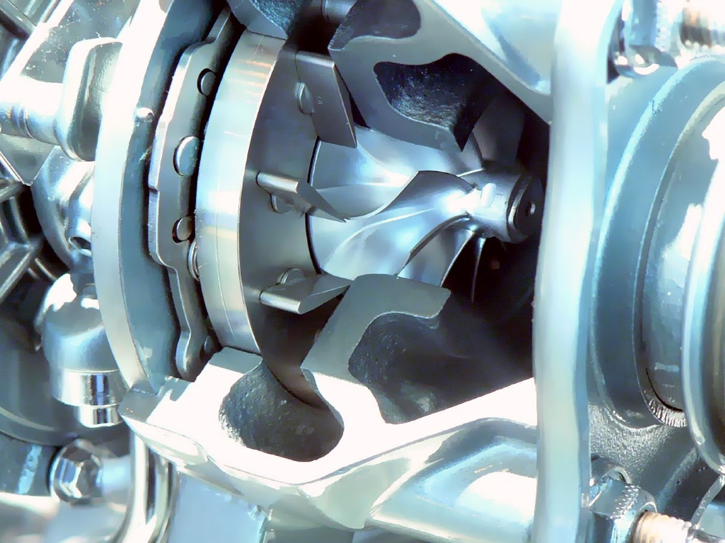
A characteristic shortcoming of turbochargers is turbo lag, in other words the delay in the turbocharger’s response. When accelerating from low engine speeds, the exhaust gases do not yet have the energy needed to overcome the inertia of the turbine wheel and compress the air as the driver is asking it to. That request can only be met a certain amount of time after the throttle has been opened. To get around this delay, solutions such as fitting turbines in parallel or in series have been adopted. With the parallel layout, smaller and therefore lighter turbochargers are used, capable of a sharper response and together supplying the required boost pressure. With the series layout, two turbochargers of different sizes operate according to engine load: at low load only the small turbocharger upstream is brought into play, while at high load the larger one is brought in as well, by bypassing part of the exhaust gas that would otherwise be reserved for the smaller turbine. Another measure is the use of variable geometry turbines. Around the turbine wheel there are vanes whose angle is regulated by a suitably programmed control unit. At low engine speeds the vanes are angled so as to reduce the passage opening. The restricted passage allows the gases to take on a direction and a flow rate that favour a change in the inertia of the wheel. It is in fact more efficient to have several small, well-directed jets than a single large but dispersed one.
Pictured: detail of a variable geometry turbine
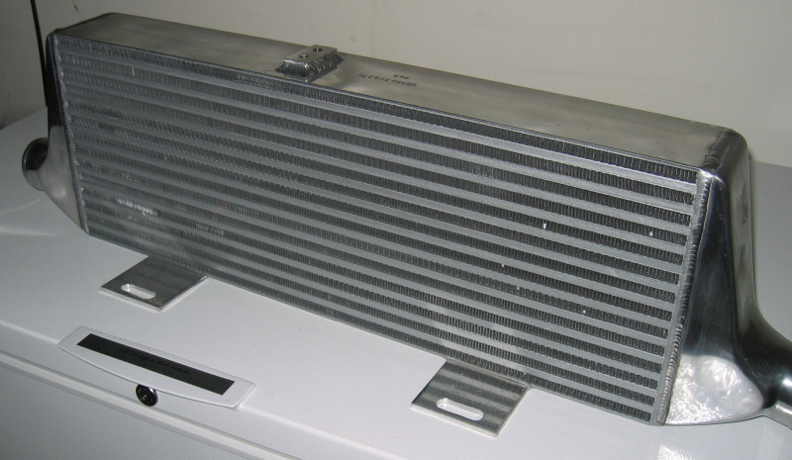
Compressing the air is not in itself enough to guarantee the air density needed for the engine to reach a specific level of performance. The sudden compression of the air, and the heat transferred from the turbine through the body of the turbo, cause its temperature to rise, which reduces the density compared with the design values. To allow the engine to receive the air density intended, a heat exchanger, or intercooler, is placed between the turbo and the engine. The intercooler can cool the air, and therefore increase its density, using ambient air (air-to-air system) or the coolant (air-to-water system).
Pictured: intercooler
Turbocharger image taken from “Motori ad alta potenza specifica”, by Giacomo Augusto Pignone and Ugo Romolo Vercelli, Ed. Giorgio Nada
Compressor detail photo by Freonr2 at English Wikipedia, CC BY 2.5, https://commons.wikimedia.org/w/index.php?curid=1920185
Turbine detail photo by Freonr2 at English Wikipedia, CC BY 2.5, https://commons.wikimedia.org/w/index.php?curid=1880641
Variable geometry turbine detail photo by User:Ton1 – own work, CC BY-SA 3.0, https://commons.wikimedia.org/w/index.php?curid=1242282
Intercooler photo by Freonr2 at English Wikipedia, CC BY 2.5, https://commons.wikimedia.org/w/index.php?curid=6570150