

In terms of masses, every car is usually thought of as a system of two masses: the unsprung mass (tyres, wheels, brake discs and so on) and the sprung mass (chassis, engine, differential and so on). The suspension sits between these two masses, which is why it matters so much to the way the car works. The suspension is in fact a set of linkages through which the unsprung mass is tied to the chassis, allowing every manoeuvre the driver can perform with the car, namely accelerating, braking and steering. Besides this function, the suspension has to guarantee:
• Road holding, in every condition the driver can control.
• The definition of the car’s set-up through its characteristic parameters (for example camber angle, toe-in and so on).
• Comfort for driver and passengers, absorbing and damping the impacts coming from a rough road.
In general, suspension systems are classified into three groups:
• Independent suspension
• Dependent suspension
• Semi-independent suspension
Independent suspension
Independent suspensions are linkages in which the wheels on the same axle are controlled by mechanisms kept separate from one another by the car’s chassis. This means that the behaviour of one wheel on the axle is independent of the behaviour of the other. Within this type of suspension, the most widely adopted in the automotive sector, the choice between one layout and another is dictated by the requirements and the responses expected of the car at the design stage. If the aim is to design an affordable, compact car, the MacPherson strut suits that objective. (Pictured: the MacPherson suspension)

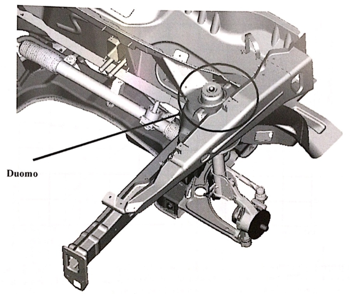
This layout uses the damper as an integral part of the suspension, which frees up more space for a transverse engine installation. It is a suspension that can be built from a small number of parts that are easy to produce, an important feature when it comes to keeping costs down in series production. Even with these advantages, the MacPherson still has a structure that transmits vibration into the bodyshell, because of the upper mounting point on the strut tower. Among the independent suspension options available, the MacPherson produces large camber changes when the wheel moves vertically, which has a negative effect on the car’s stability and set-up. On top of that, a damper rod mounted in this way is subjected to bending loads that can cause sliding friction against its cylinder or outer tube. (Pictured: position of the strut tower on the bodyshell)
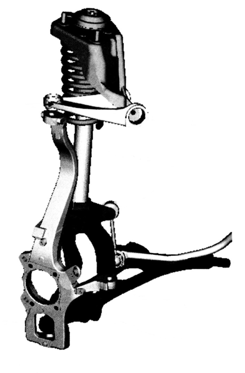
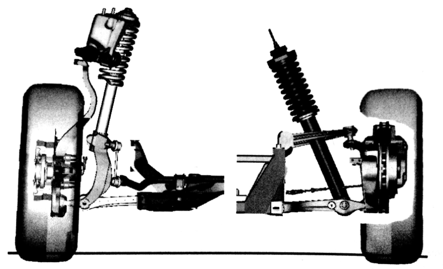
A technically better solution than the MacPherson is the double wishbone suspension, thanks to the fact that it uses two arms connected to the chassis, one lower and one upper, which spares the damper from having to perform a structural job as well, to the benefit of ride comfort. The structure adopted keeps the set-up parameters within a narrower range when the wheel moves. Usually, given the mid-engined layout and the higher costs caused by a greater number of components, this solution is adopted on Grand Tourer cars. For high performance cars with a transverse front engine, the high upper arm configuration can be used in order to reduce intrusion into the engine bay. Furthermore, as the number of components in this solution increases, so does the number of joints in the linkage, which can wear, altering the set-up and causing uneven tyre wear. (Pictured: 1 – the double wishbone suspension in the high upper arm configuration 2 – the two types of double wishbone suspension: with high upper arm (left) and low upper arm (right))
The virtual centre suspension deserves a mention of its own. In a conventional double wishbone, the upright is hinged to its arms by two ball joints that define the steering axis. This means the steering axis is heavily constrained by the position of those joints, making it impossible to set a small or negative scrub radius, which are useful respectively for reducing the torque felt at the steering wheel and for a reactive steering response, above all on front-wheel-drive cars, which generally understeer. (Pictured: example of virtual centre suspension applied to a high double wishbone layout)
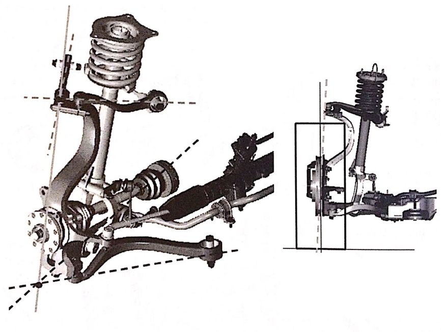
In the virtual centre suspension, the axis is defined by two points, at least one of which is found at the intersection of the axes of two separate links that take the place of the traditional arm, as shown in the figure above. This solution makes it possible to solve the scrub radius question, although it does mean adding a ball joint to the upright and using curved links because of packaging requirements while the wheels are turned.
For the rear axle there is the trailing arm suspension. Here the suspension takes the form of two swinging arms hinged onto a crossmember made up of two pressed sheet metal shells, joined to one another by a circular section beam. The whole assembly is connected to the bodyshell through rubber bushes. Spring and damper are located in the space between the arm and the sheet metal. (Pictured: trailing arm suspension)
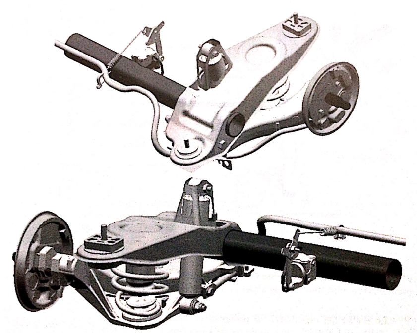
As can be seen in the image above, the solution is not bulky and frees up space for the fuel tank and/or the spare wheel. The components used are light, which keeps unsprung mass low, with benefits in terms of comfort and handling. Manufacture and assembly are also easy and inexpensive. On the other hand, the arms can deform under lateral loads, contributing to oversteering behaviour in the car, and camber recovery is not guaranteed.
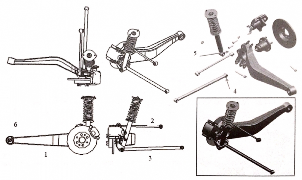
To ensure better stability when the suspension is under load, the guided trailing arm layout is adopted. As can be seen in the image below, the stiffness and stability of the suspension are provided by links 2 and 3. Thanks to this arrangement, camber recovery becomes possible when the wheel moves, although adding more elements to the suspension brings greater build complexity and higher costs. (Pictured: guided trailing arm suspension)
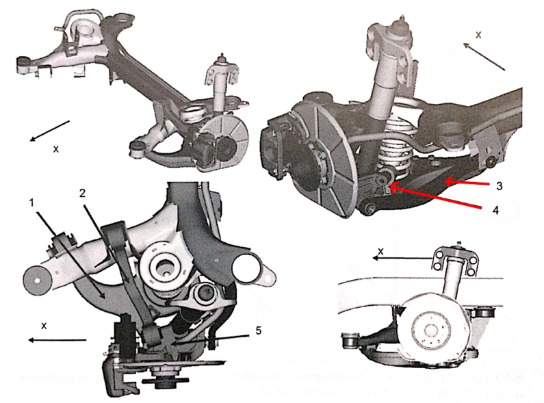
The multi-link suspension is a technically complex solution, in which the upright is connected to the bodyshell by five links that allow only vertical movement of the wheel. Looking at the image below, the only movement permitted is made possible by the toe link (link 3), which prevents the wheel from steering about its own axis. This solution stabilises toe variation and provides camber recovery. On the other hand, it is a complex and expensive layout, and highly sensitive to wear in the rubber elements. (Pictured: multi-link suspension)
Dependent suspension
The only member of this category of suspension is the old leaf-sprung live axle. Referring to the image below, the uprights are connected by axle 1. The leaf springs 2 are attached to the axle by flanges and bolts. The leaf spring is tied to the body by the fixed eye 3 and by the shackles 4, which allow the spring to deform as the wheel moves. Clearly the live axle is simple to build and guarantees full camber recovery. But it does not allow camber and toe to be adjusted, it does not have high roll stiffness and it does not deliver much comfort. (Pictured: live axle suspension)
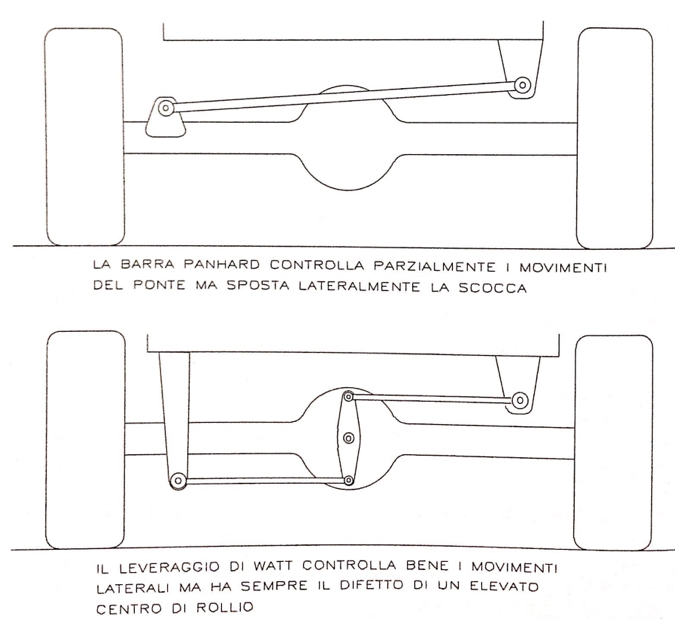
To improve the kinematics of the live axle, certain measures are adopted that consist of using particular linkages. Below are two examples of how this is done: the Panhard rod and the Watt’s linkage. (Pictured: examples of guided live axles)
Semi-independent suspension
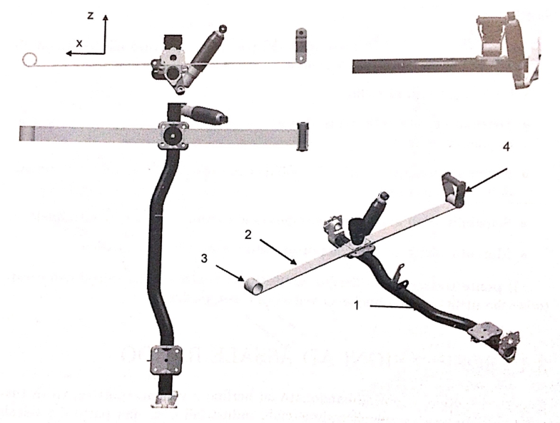
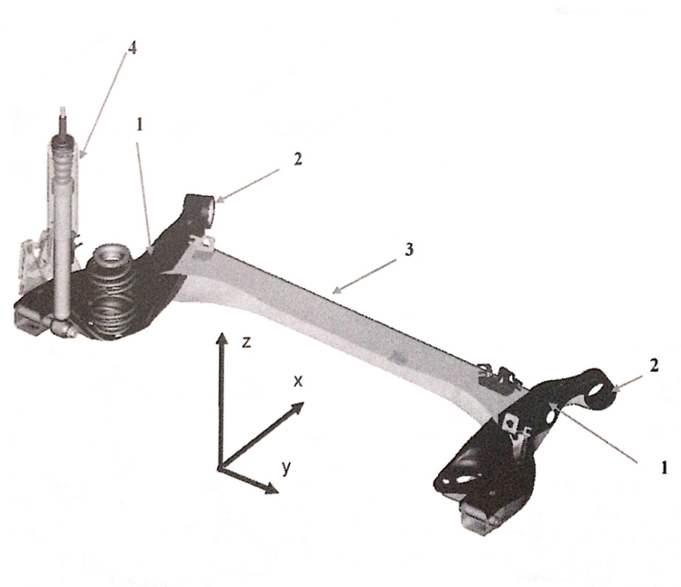
The only solution in this category is the torsion beam axle. The wheels are semi-independent because the swinging arms 1 are connected to one another by a profiled beam with a certain degree of torsional compliance. It is a simple solution to build and to assemble. It allows lower unsprung masses and keeps camber and toe under control. That said, the beam is an elastic element under stresses that can compromise its function, and it has low roll stiffness. (Pictured: torsion beam suspension)
Images taken from “L’Autotelaio-Progetto dei componenti”, by Giancarlo Genta and Lorenzo Morello, Ed. ATA
Images of the MacPherson suspension and of the examples of guided live axles taken from “L’assetto-Teoria e pratica per la messa a punto dell’assetto”, by Flavio Facchinelli, Ed. Motor Books Tech